
Converting Circuit Boards to 3D CAD
There are a lot of tools out there that allow you to design circuit boards, but anyone who has been doing engineering for a while has encountered the problem of integrating mechanical and electrical design. If you don’t design your mechanical system until your circuit board is done, it’s likely to be expensive and make no sense. If you design the mechanical system before the circuit board, it will similarly bump against silly constraints. So instead, it is critical to develop these things in parallel so that both mechanical and electrical designs have constraints from each other integrated at an early stage.
The nicest way to do this would be if I could take my existing circuit board software, click a button, and have it output a file including models of my components which I could import directly into Solidworks. And then be able to make mechanical design changes to the board in Solidworks which feed back into the circuit board software. This solution is, however, extremely expensive – so how do you do it if you’re a small business or hobbyist?
My conclusion is that it is completely unrealistic to get full bidirectional CAD conversion, but that it is possible (barely) to get unidirectional conversion from a circuit board to a 3D model.
The starting point
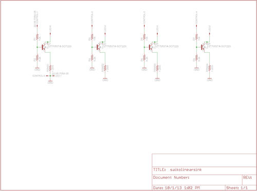
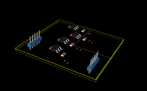
To investigate this, I designed a very simple circuit board using EagleCAD, my long-standing partner in circuit design. It is a board that converts four TTL level control signals into high current linear outputs capable of driving very large loads as a current sink.
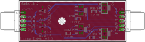
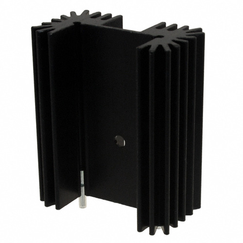
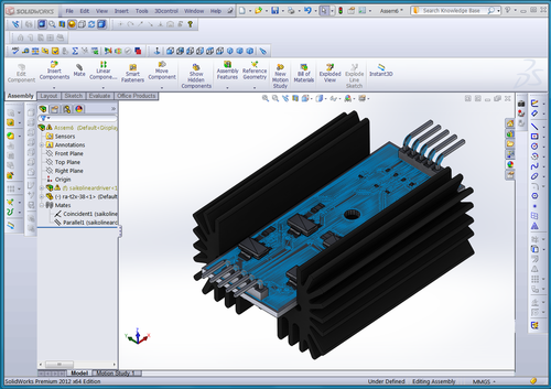
On the mechanical side, the intent to integrate this design with a heat sink suitable to dissipate the power required. This board, for scaling, is 1" wide and 2.5" long, so it is actually quite small.
I was easily able to generate a 3D graphic of the board alone using this fantastic tool.
Using this tool with my directly exported Gerber files from Eagle, I was able to generate this board rendering with no effort in about five minutes of work. Great and easy start, but no 3D geometry for SolidWorks, and no components. Still, very grateful for this fantastic tool!
My goal was to be able to get this design into SolidWorks as a STP or IGES file with rendered components. In my design, there are only four packages present, all extremely common – 0402 resistor, 1206 resistor, SOT223-4 transistor, and five pin header – so I figure if I can’t do it with this, it’s not realistic for anything.
My second goal was that it be something renderable into a “nice looking” image of the board. This means more than just an extrusion of the footprint.
Results
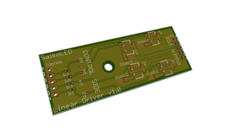
In the end, I was not able to get a single solution to produce a valid STP or IGES file directly. I was, however, able to get a reasonably nice VRML output of the board and components which I was able to convert through multiple intermediary files into a mostly valid STP file with real geometry. Unfortunately, this conversion lost a lot of information that would make it easy to generate a “pretty” model of the board (color mostly). Generating a 3D image of the board alone (no geometry imported) was quite easy using DipTrace, and I’m very pleased to have found that tool.
Option 1: EagleUP + Sketchup
This option was the first one I ran across, and initially looked very promising. Sketchup appears to be a well developed tool, and EagleUP was possible to integrate directly into EagleCAD. Eagle itself advertises the ability to generate 3D models of their boards in this way.
However, it doesn’t work well for component placement, and Sketchup is expensive. ($590 for business) I did use the trial, and it did an okay job with board import. The basic issue with import was that it did not manage to match even these four very common packages, and had no mechanism to let me substitute in alternates with an easy search interface.
The “correct” way to do this, to me, would be to give you a component by component dialog where you can search through the database that they have and swap in designs from their database that match your design. It seemed like they may have been moving towards this solution, but the interface leaves a lot to be desired and I was completely unable to figure it out. Feel free to leave comments if you do!
https://store.sketchup.com/product-view.ep?pID=COSU2013NEW
Option 2: The Direct Method (DXF Export and extrusion)
I’m not an expert at SolidWorks, but I did get paid to do it for a while. So I’m not bad. I’ve imported plenty of DXF profiles and extruded them into various shapes as needed, so I figured this might work for circuit boards. Even better, Eagle has a ULP to export as DXF! I figured that if I could do this and export a centroid database of parts, I could at least manually add parts for the most important components inside of Solidworks and fairly quickly place them.
Unfortunately, there were two big problems with the DXF files produced. First, the traces were all converted into lines without width. Second, certain types of pads were also converted without width. Third, my ground plane pours were converted into horizontal hatching that made no sense.
It is possible that I could have converted all of this into a valid 2D profile of the copper pour layer, but it was clearly going to be a ton of work. I’m not sure if this is an Eagle specific problem, but I know that DXF files certainly can be created which would work. The ones from Eagle just didn’t.
I also tried doing this with Gerber as an intermediary, but achieved an identical result. The Gerber files, although they rendered properly in Gerbv (gerber viewer for Linux) were still made up of width-less traces and horizontal hatches when exported as DXF.
Option 3: IDF export from Eagle
This looks like it is actually a pretty good option if you just need simple footprints. IDF is a file format designed specifically to be an intermediary between electrical CAD (like Eagle) and mechanical CAD (like SolidWorks). The output models are not pretty though, just correct bounding boxes that you can design in. For just mechanical design, this might actually be totally fine, so definitely consider it.
In terms of workflow, it was very easy. For anyone with significant experience with Eagle, the tutorial linked was quite straightforward. However, my goal of making something possible to render into a realistic looking board is not met, and since that is a big goal for me I did not go further for now.
http://www.iheartrobotics.com/2009/04/ecad-vs-mcad-round-1-fight.html
From what I can tell, this may also require importing using a very expensive SolidWorks Professional/Premium feature called CircuitWorks. A friend attempted to get this to work, but it did not go easily so I am not inclined to spend a lot of time trying to get access to the feature. Even getting a demo version looked like a pain.
Solidworks, call me if you want to help ;-)
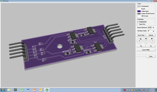
Option 4: DipTrace with 3D Visualizer
DipTrace was recommended as an alternative software suite for circuit board design which has a built in 3D component model library. It worked quite well for making a 3D graphic of the board! However, I was completely unable to get it to export into a mechanical CAD friendly format like IGES or STP. I was able to get it to export as VRML and eventually convert to a (very large and unoptimized) STP file without color information which I was able to use in SolidWorks (sort of).
I’m willing to consider switching Circuit Board software from EagleCAD. I’ve been using Eagle for seven years, and would consider myself an expert user. However, while I have a professional license for version 5, I have never been inclined to spend another $1640 in order to get an equivalent license for version 6. The less expensive versions of EagleCAD, while available, do not allow commercial use.
On the other hand, DipTrace offers lower tiers of their software which are not board size limited (instead just number of layers and pins), and which are allowed for commercial use for prices ranging from \$75-895. For a \$145 price level I could probably make the majority of circuits needed for SaikoLED, and at \$345 it can handle 4-layer boards as well.
To get from EagleCAD to DipTrace, I used the DipTrace provided ULP inside of Eagle. The result was quite good. I found DipTrace to be very easy to use, and was quickly (and without a manual) able to replace the mechanical packages for the devices on the board with devices from their reference library.
After updating each of the individual packages to match one in the DipTrace standard library, and installing the 3D models, I was able to quickly and easily render a 3D model of the board.
I did have to find a model for the five pin header, which was not included in their library. To do this, I first downloaded a STP file of the part from the manufacturer’s website. Then I followed the instructions here:
http://www.pcblibraries.com/forum/3d-step-to-vrml_topic976.html
to identify FreeCAD as a good tool for this. Using FreeCAD, I was able to quickly import the STP file, and then click the geometries to export a mesh of the STP file as a VRML file. I was then able to open this in a convenient part making dialog inside of DipTrace to produce the parts as shown in the model above. The process took perhaps 15 minutes, including the learning curve for using the model generation tool.
The big downside of the DipTrace approach is that it only allows export at VRML. This is a pretty major showstopper for integration into SolidWorks. I tried importing into SolidWorks via several techniques, including attempting to convert the VRML file into STL using FreeCAD, but the memory requirements for such a complicated VRML model (~22,000 faces even for just this simple board) consumed all of the memory on the SolidWorks machine without ever accomplishing a successful import.
The only way I was able to get the part into SolidWorks was by importing as a “graphical” model, which meant no geometry import. This isn’t the end of the world, as at least the model is inside of SolidWorks; however, it doesn’t represent apparent faces as actual geometrical faces, so it was not possible to do things like mate the board with my heat sink or a case.
On the plus side, I can output a reasonably nice looking model with components included through other VRML editing tools such as Blender, so for making a mock-up rendering, this seems to be a satisfactory solution. With luck, DipTrace is working hard on STP output though! It is probably reasonable to take my heat sink and convert to a VRML device to add as a part to the board, although this solution is not a great one in the long term.
This VRML file was possible to open inside of Linux (my preferred work operating system), where it appears like this. I opened it by using “mesh import” to directly open the .wrl file.
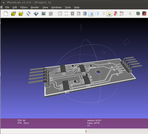
As you can see, it lists 20,799 faces and 62,337 vertices (so it’s no wonder SolidWorks choked on the file conversion). Additionally, the output to VRML lost color information somehow (it was purple in the DipTrace viewer). It did keep grayscale color, so I am not sure what happened in the conversion. However, the VRML file is clearly grayscale.
From here, I attempted to follow the instructions in this video to convert the mesh into a 3D model.
I found that directly importing the VRML file into FreeCAD (it seemed to be supported) resulted in a non-solid board. Not entirely clear if that’s a showstopper or not ultimately. Instead, I found I needed to use the FreeCAD Ubuntu PPA to get version 0.13 so that the conversion through the Collada format worked. Version 0.12 unfortunately didn’t let me get very far because the “Create Shape from Mesh” button was greyed out. I don’t know if this was due to improper VRML importing (or exporting from DipTrace) or if it was just because the older version wasn’t so good. However, with version 0.13 and Collada as an intermediary format it imported and allowed me to use the command. After importing the .dae Collada file and creating a shape from mesh as described, FreeCAD looks like this. It’s now lost all color information.
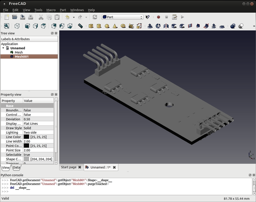
At this point I selected the part Mesh001 and used “Export CAD” to save it as a STP file. So far so good, sans the color information. From here, importing into SolidWorks was actually fairly smooth (all things considered). It did take several minutes even for such a simple board, and had a “CASCADE” error in the conversion, but this didn’t seem to prevent it from mostly importing (with errors).
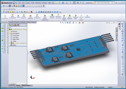
which, for the first time, actually meets almost all of my goals! It has real geometry! To prove it, here is me mating the imported STP model with my heat sink model!
Option 5: KiCAD with 3D Visualizer
I tried doing this with KiCAD as well as DipTrace. Unfortunately, the Eagle to KiCAD converter is hopelessly out of date and did not work at all for me. Instead, I attempted to reproduce the basics of the circuit. This actually worked quite well, with built in 3D models for all four devices!
I found KiCAD awkward to use, unfortunately, compared to both Eagle and DipTrace, and don’t think I could use it for actual work. Even simple things like deleting erroneously placed lines took a tutorial since simply clicking the delete button and then clicking the errors didn’t work.
The 3D rendering was primitive compared to DipTrace, with the board transparent. A major advantage was that it worked in Linux, whereas I have to run DipTrace in VMware. However, this advantage is not sufficient to convince me to use this seemingly very awkward tool. Perhaps in a few years.
Conclusions
Electrical CAD to Mechanical CAD conversion has a long way to go before it will be very good. However, it’s come an awfully long way. The IDF file format looks to me to be largely too immature to use in anything useful, but if you have the $7k+ to spend for some serious software it may be feasible. For a small company like SaikoLED, this isn’t practical yet.
A primary use of CAD for us is to make mockups to show customers, so something that is reasonably quick and shows a real-looking circuit board is important. For this, the use of DipTrace was the best, and allowed us to quickly and easily generate a 3D colored graphic that looks nice and has real part models. Where DipTrace failed is that they use the VRML file format for generating the 3D model. This is fine to just show a model of a circuit board, but falls short when you are looking to integrate the circuit board with other mechanical models.
Examples of where this is important are, for instance, adding optics to your model to make a realistic looking LED light, or a case around the board so that it is less abstract.
At this point it seems to be feasible, if awkward, to convert from DipTrace (or any other software that produces a VRML model) through the use of MeshLab followed by FreeCAD to create a STP file. Unfortunately, in the process all color information is lost meaning that I would need to manually add that back in inside of of SolidWorks. However, I have to do this with enough manufacturer supplied packages that while not fantastic it might not be too much of a barrier. Additionally, there were errors in importing the STP file produced by FreeCAD inside of SolidWorks, which appears to be done with something called OpenCascade. I believe that OpenCascade is the library used by FreeCAD to output the STP file. However, the errors did not prevent import, and looked like it may be reasonable to manually correct them.
So, if any circuit board CAD programs (especially DipTrace, which I’m very strongly considering switching to now!) are listening, please take a look at STP output directly! STP files can incorporate color information, and directly outputting data from your software will result in much higher fidelity and much smaller complexity files as compared to using VRML as an intermediary format.
——————
Brian Neltner is a scientist, artist, karate instructor, and entrepreneur in Somerville, MA. http://neltnerb.tumblr.com/bio