
TeensyLED Board
This week I learned about a really neat trick to speed up current sinks built out of BJTs. There is an issue with getting them to turn on and off really fast, which is that if the impedance to the driver is too high impedance, it has a very long turn on time.
In comes something called RCTL logic – Resistor-Capacitor-Transistor. The concept is actually surprisingly simple, instead of using just a resistor between your driver and the base of the BJT, you use a bypass capacitor as well so that when the driver signal changes suddenly, that signal makes it with low impedance to the BJT base without requiring a large static current for steady state operation.
With this, I managed to design a system that will let you switch 700mA of current directly from a Teensy 3.1 with a fast enough rise time to make 100ns pulses workable. With 100ns pulses, this means the new design can support full 16-bit PWM at 150Hz, or 8-bit PWM at 39kHz!
Using the ZXT1053AK, I developed this model circuit to demonstrate how it works.
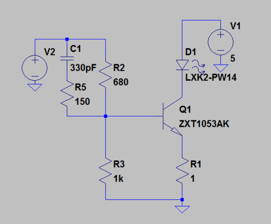
The basic idea principle of operation is the same as the SaikoLED super inexpensive linear current regulator. The sense resistor at the setpoint 700mA provides 700mV at the emitter. The BJT Vbe is about 0.7V, so the idea is to set the base at about 1.4V using the resistor divider, which defines a feedback loop. It’s not very precise, but it is cheap. In this circuit model, the resistor values are shifted from a 1.4V divider because of current going into the base of the BJT, and are selected using this spice model. The old SaikoLED linear current sink just had this resistor divider.
The limiting factor on BJT switching speed in this circuit is the amount of charge I can deliver to the base of the BJT, in other words, the impedance to the driver. However, lowering the resistor divider values by 10x won’t work because now the digital controller is being asked to provide too much current. You can try to work around this using buffers, but there’s a better way!
By adding in the bypass capacitor, a sudden change in the driver signal is passed to the BJT base through a low impedance path, which can be set independently of R2 and R3. So now instead of having to choose between drawing a lot of current from my digital IC and a slow switching time, I can get both!
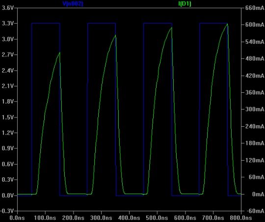
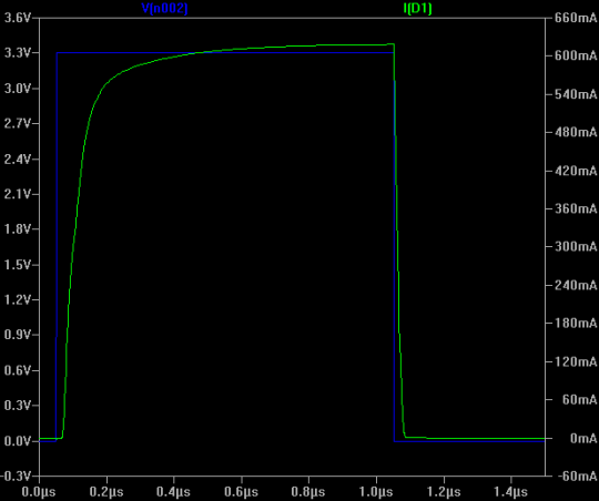
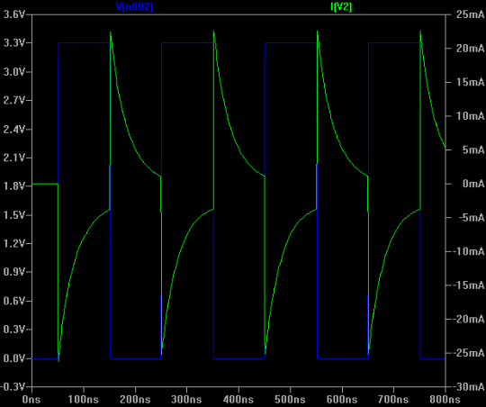
Check out the simulation results, for 100ns pulses, 1us pulses, and the driver current below.
100ns Pulse Response
1us Pulse Response
Driver Current
For more information, check out the project documentation and design files on GitHub!